
Today I thought that I should step out of my normal blogging content and share some of my personal pet project and hobbies. I always been keen of tinkering, testing and building things - being software, hardware, or our house or garden. Over the last few years I’ve been trying to make as much things as possible “smart” in our houses, and particularly in my home office. This home automation project consists of tons of different third party options, but also quite a few devices and gadgets that I built myself. A couple of examples; I’ve built quite a few temperature and humidity sensors that are placed around the houses, door sensors, I have a few old refurbished computer fans that are controlled by these sensors to force air in or out of the rooms, I have a custom built “meeting traffic light”, a purpose built screen with sensor details and notifications. Most of these custom devices has one thing in common - they are based around the ESP8266/ESP32 chip, programmed with ESPHome and orchestrated by Home Assistant.
About a year or so I bought a cheap video light, to improve the light when having video calls. I got a Vijim VL81 LED light (about $16). It worked great for my home office. But each and every time I wanted to use it I had to stretch over to where it’s mounted and turn a knob on the back of it. Doesn’t sound like a big thing, but this small thing always moved it a bit out of position so I had to readjust it, and as time passed I just stopped using it. Since it’s powered by USB I figured out that I could actually put one of my ESP-12F microchips into use - and guess what it worked perfectly. And this is how I did it.
DISCLAIMER: As usual, this setup and these components works for me. I took parts that I already had at home. There’s likely many ways to optimize or make this build better. Feel free to add comments or upgrades in the comments section.
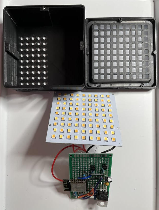
Disassembling the Vijim LED Light
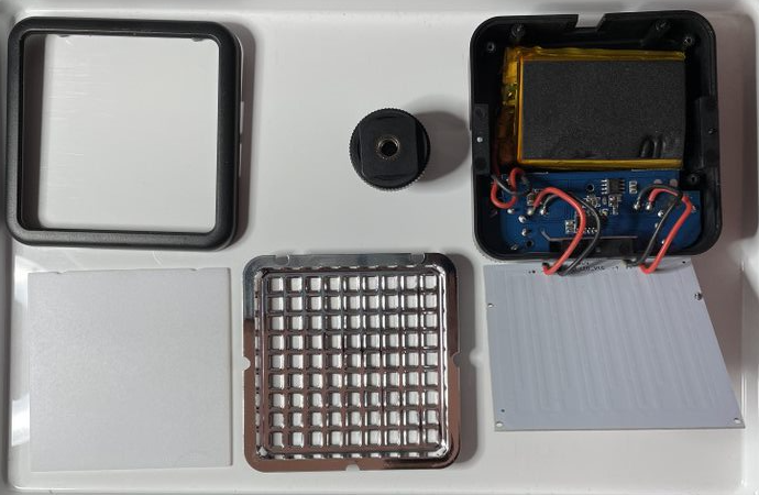
I started with disassembling the LED lights and inside there was the LED lights I wanted to reuse. It’s a 9x9 matrix with a combination of white and yellow LEDs that allows you to create a great backlight for video sessions. I unsoldered the LED matrix panel and did some tests on it to ensure I grasped how it worked (well, it’s a LED light…). I also decided not to keep the casing - it was just a little bit to small for me to build a prototype around (and has nothing to do with that I cracked it a bit when removing the knobs). Instead I decided to keep the mount - which fitted perfectly on my monitor, and the grid and diffuser for optimal light, and create a custom 3D printed case (mor on this later).
Using an ESP-12 to drive the lights
My absolute favorite microchip is the ESP-12F variant of the ESP8266 family. It’s very compact, has Wifi, runs on 3.3V, versatile and cheap. If you buy a bunch of them it’s about $2 per chip! You can get away cheaper by using ESP-01, but the ESP-12 has more memory and allows for updates over-the-air (OTA) using ESPHome, which you can’t do with ESP-01.
The ESP-12F requires 3.3V to run, but USB gives us 5V, so to get that to work I needed a voltage regulator and I used the LD1117 I had at home. This regulator in combination with two capacitors, for stability, is my go-to setup for almost all things I build.
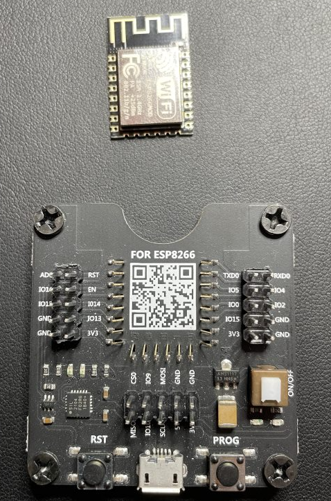
To get ESPHome on to my ESP-12, I need to use a programmer hooked up to my computer via USB. With ESPHome, you only need to have this connection the first time, once I have it on my network I can do OTA updates. You can buy a programmer on Amazon (or wherever you prefer), and even get them bundled with a couple of ESP’s. You can also get the WeMos D1 mini modules, that makes the soldering and programming easier, but takes more space, if you want to.
To get the correct max luminosity of the LED matrix I could not drive them using the GPIO ports on ESP-12 - remember this is a 3.3V device and there’s not enough current output. Instead I use the GPIO ports control a transistor (2N2222A NPN transistor), that drives 5V through the LEDs. In order to control the luminosity level I use the PWM (pulse-width-modulation) output feature of ESP8266. That is we turn on and off the LED with pulses to control the luminosity. I used two ports for this, one for the yellow parts of the LED and one for the white parts.
I decided to not use a physical button on this gadget, even though it would be very easy to do by using one of the other GPIO’s. Instead this light will be controlled via Home Assistant, more on that later.
Configuring ESPHome
I prefer using ESPHome for configuration of these small gadgets, over using Arduino studio to program them. Programming with Arduino is fun, and I have several of those projects, but ESPHome give me results so much faster and also directly integrates into my Home Assistant setup. Below is some of my ESPHome configuration for this gadget, and you can find a full version of it in the Github repo.
First I need to specify the chip to use and the base settings for the device. I also configure Wifi, Home Assistant connection, OTA updates as well as logging. Once this is flashed on the device you no longer need the programmer.
# Chip config
esphome:
  name: Office Video Light
  platform: ESP8266
  board: esp12e

# Enable OTA updates
ota:
  password: ${apipassword}

# Enable logging
logger:

# Enable Home Assistant API
api:
  password: ${apipassword}

# Configure Wifi and Wifi AP
wifi:
  ssid: ${WifiName}
  password: ${WifiPassword}

  ap:
    ssid: "${name} Hotspot"
    password: ${appassword}
To flash the device you just use the ESPHome Python CLI like this. If your USB is connected correctly you will be asked to flash via USB or over Wifi.
NOTE: If you’re using a programmer you might need to install the correct USB drivers for that device.
esphome run video_light.yaml
To control the GPIO ports for the white and yellow LED lights I define two outputs, on GPIO05 and GPIO12 using the PWM platform.
output:
  - platform: esp8266_pwm
    pin: GPIO05
    frequency: 1000 Hz
    id: pwm_output_yellow
  - platform: esp8266_pwm
    pin: GPIO12
    frequency: 1000 Hz
    id: pwm_output_white
To control these two outputs I use a combination of a ESPHome light entity and a number entity. The light entity gives me a switch in Home Assistant to turn the light on or off and the number entity gives me a slider in Home Assistant to control the intensity of the light. When the number is changed I use an ESPHome lambda function to convert the number value into a value between 0 and 1 that is sent to the GPIO port.
light:
  - platform: monochromatic
    output: pwm_output_white
    name: "White Light Switch"

number:
  - platform: template
    name: White Light Intensity
    min_value: 0
    max_value: 100
    initial_value: 100
    step: 10
    id: led_intensity_white
    set_action:
      then:
        - logger.log: "White intensity changed"
        - output.turn_on: pwm_output_white
        - output.set_level:
            id: pwm_output_white
            level: !lambda |-
              return x/100;
This is the version 1 I’m using for this, and I already have a few ideas on how to improve this. For instance, make one slider for light intensity and one that moves the color between yellow and white.
Connecting it all together
We’ve now gone through the main parts - getting all components, converting voltage, programming the chip - and it’s time to wire it all together. I highly recommend that you do this on a breadboard to start with - DO NOT start soldering.
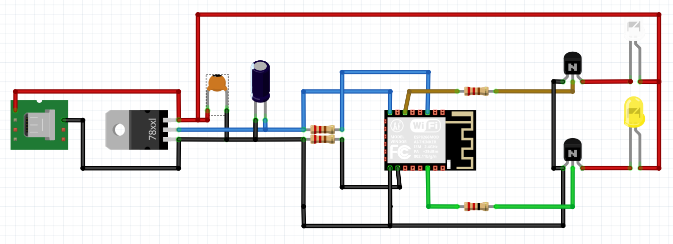
To get the ESP-12F to boot, without the programmer, you need to pull-up the EN pin (so it has the value of 1), and pull-down the GPIO15 pin (so it has the value of 0) with resistors (I used 10k). If you use pre-built modules such as the D1 or NodeMCU this is not required.
Then it’s more or less just connecting the wires and this is how it looks like:
And finally when you’re done, you can actually solder it onto a PCB board, or even go the extra mile and make a custom PCB (I already started this, for V2).
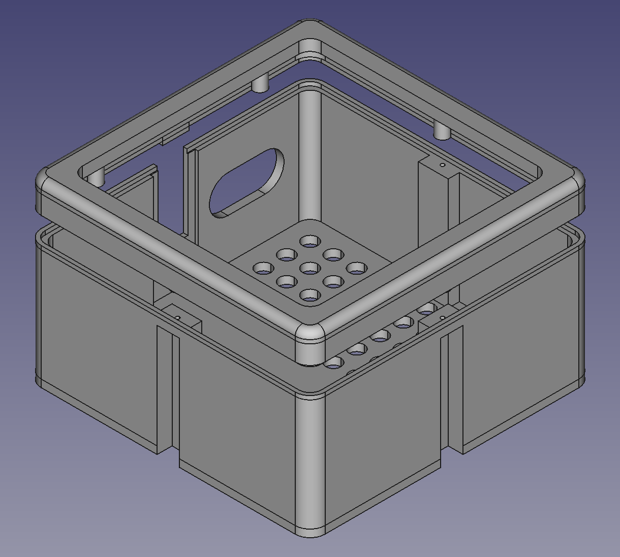
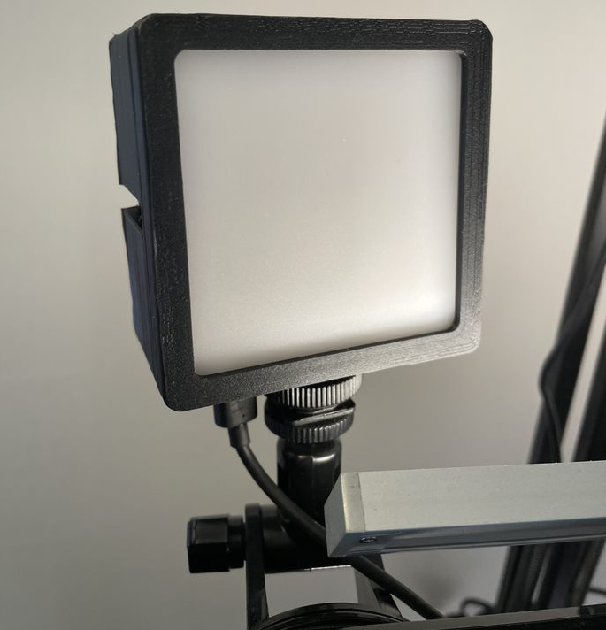
Making it look good!
To create a new casing, with better room for my PCB, I used Freecad to design a new case. A case that would fit the reused diffuser and fit on the reused mount. Finally I 3D printed this on my Creality Ender-3 3D printer, with great results. The STL files are available in the Github repo
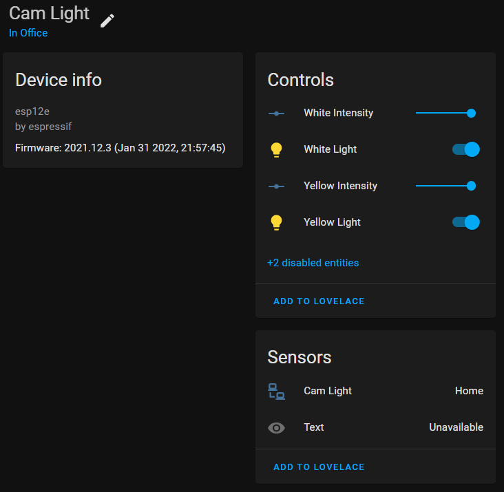
Automating it with Home Assistant and Node-red
Now, when all is up and running I connected this new device to Home Assistant (HASS). Actually Home Assistant automatically discovered my device and I just had to input the password for it. Once in HASS I could add the switches/sliders to the interface and control the video light from my browser or phone.
To go back to my original issue, having easy access to turning the device on and off, I re-used the big arcade button I put on my small display, another ESPHome powered device. In HASS I created a Node-RED automation that toggles the video lights with a press of that button. And also it will automatically turn off after two hours, that happened often that I just forgot about the light and let it run.
Summary
There you have it, this is how I turned a cheap manual video light into a smart video light solution. It’s not just a practical solution to a mundane problem, but also tons of fun that will inspire even more ideas! Perhaps I’ll post more about these things I build in the future, what do you think?
What you need
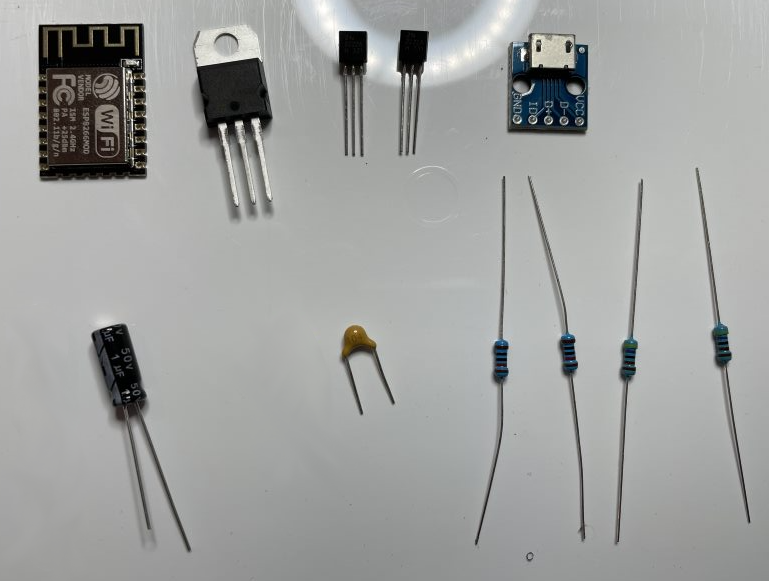
Here’s a recap and inventory of things I used:
Items
This is the complete list of items you need to get the job done, the tools I used are mentioned throughout the article.
| Item | Where to find | Cost |
|---|---|---|
| 1x Vijim VL81 LED Light | Ulanzi, or Amazon, or Ebay | $16 |
| 1x ESP-12F (or equivalent) | Amazon | $2 |
| 2x 4.7 kOhm resistors | Amazon | $0.02 |
| 2x 10 kOhm resistors | Amazon | $0.02 |
| 2x 2n222A (NPN transistor) | Amazon | $0.06 |
| 1x 100nF ceramic capacitor | $0.02 | |
| 1x 10uF electrolytic capacitor | $0.03 | |
| 1x LD1117V33 voltage regulator | Amazon | $1.5 |
| 1x USB to DIP connector of choice | Amazon | $0.50 |
| Assorted Wires | Amazon | $1 |
| Double sided PCB board of choice | Amazon | $1 |
| USB charger and cable | ||
| SUM | ~$23 |
Cost is of materials used for this gadget
Tools
This is the various tools I used to build this:
| Tool | Purpose |
|---|---|
| ESPHome | Logic and code for the device |
| Home Assistant | Control the device |
| Visual Studio Code | Editor when working with the yaml files |
| Freecad | 3D design |
| Ultimaker Cura | Slicing and printing the 3D model |